Empowered by the Ecosystem
Learning Embedded Rust with uFerris
Rust Week 2026 · May 18 · Utrecht, Netherlands
This workshop takes a different approach to learning embedded development. Instead of walking you through peripheral configurations step by step, I'll teach you how to teach yourself - by navigating the embedded Rust ecosystem, reading documentation effectively, and adapting existing examples to your own needs.
What You'll Learn
By the end of this workshop, you will be able to:
- Navigate the embedded Rust ecosystem - find the right abstractions, understand the abstraction layers, and know where to look for answers
- Read embedded Rust documentation - in the documentation, in crate source code, and in example repositories
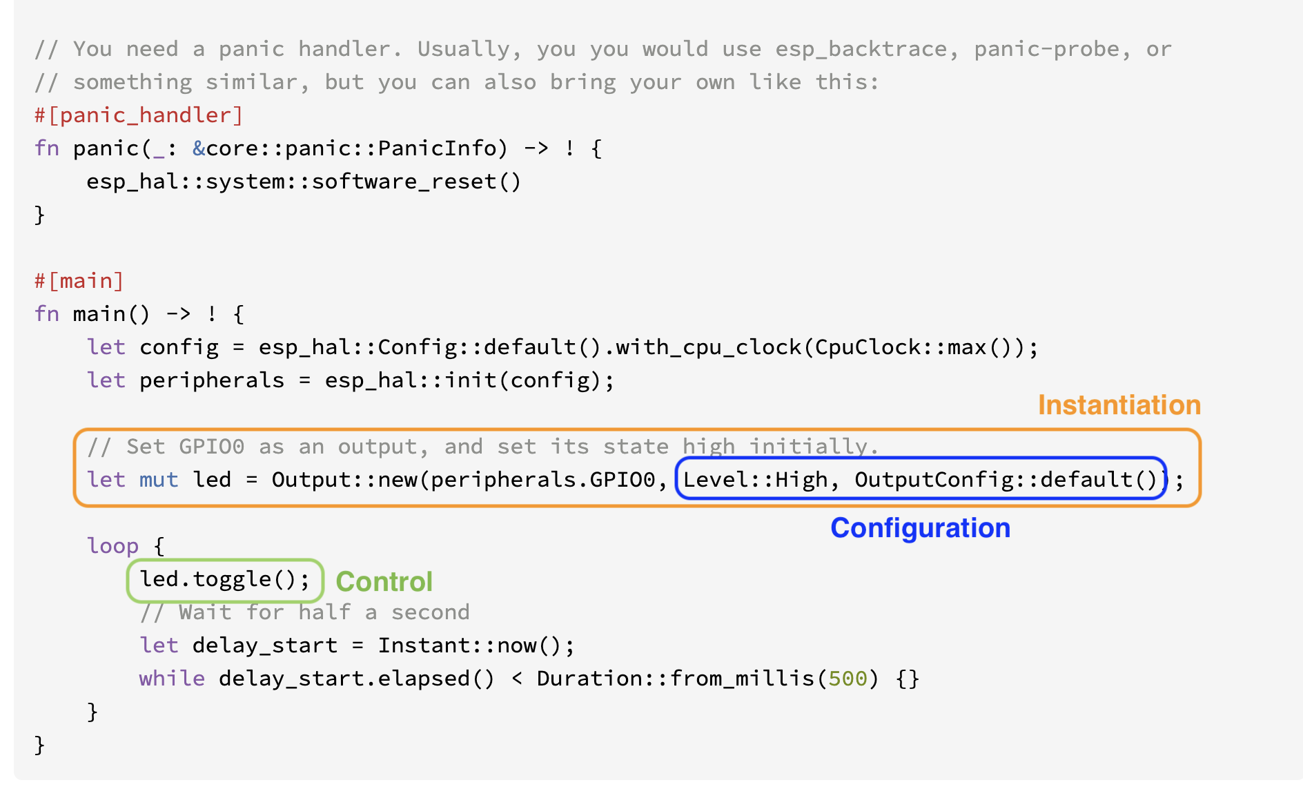
- Apply the Instantiate → Configure → Control pattern - a mental model that works for every peripheral, every HAL, every driver crate
- Adapt existing examples to new use cases by exploring configuration options and control methods in the documentation
How This Workshop Works
Every hands-on module follows the same workflow:
- Read - I give you a working example in the workshop repo
- Understand - You study the code and map it to the documentation
- Adapt - You modify the example to do something different by discovering new options in the docs
- Extend - Stretch goals push you to navigate unfamiliar documentation independently
The Hardware
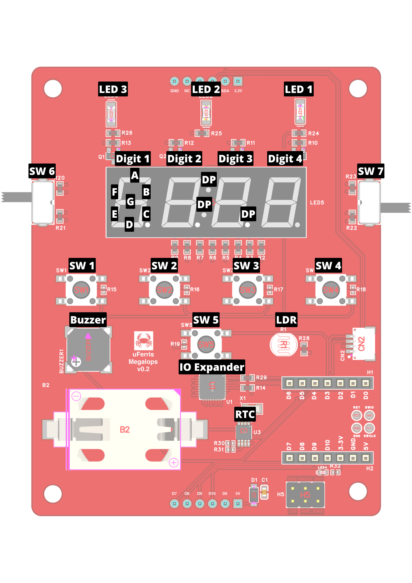
uFerris Megalops Baseboard
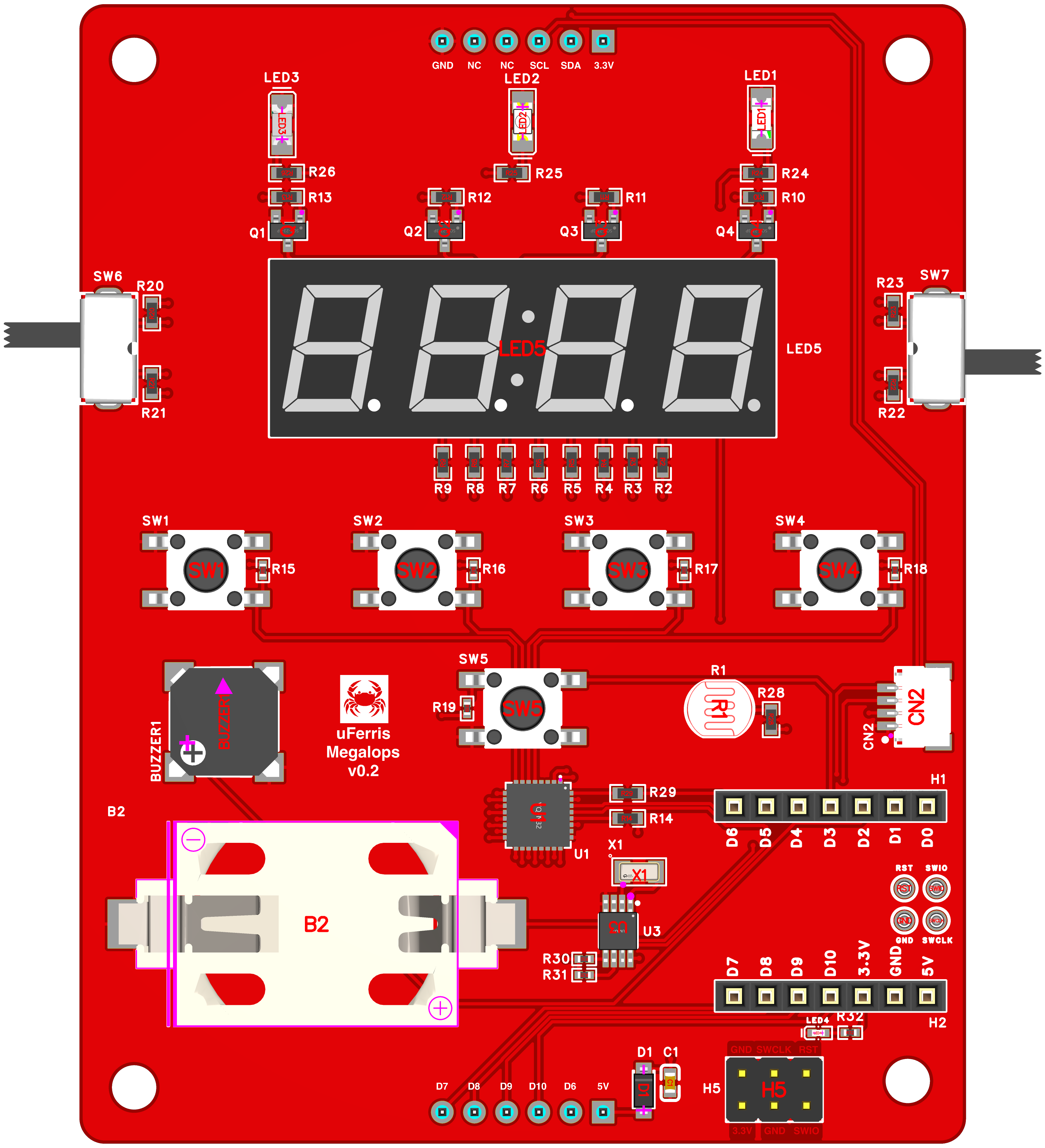
The uFerris Megalops Baseboard is a learning platform purpose-built for embedded Rust education. It's designed to give you a rich set of peripherals to explore without needing to wire anything up - just plug in and start coding.
| Component | Quantity |
|---|---|
| Buttons | 5 |
| LEDs | 3 |
| RTC | 1 |
| LDR | 1 |
| Switches | 2 |
| Buzzer | 1 |
| Qwiic Connector | 1 |
| 4-Digit Seven Segment Display | 1 |
Xiao ESP32-C3
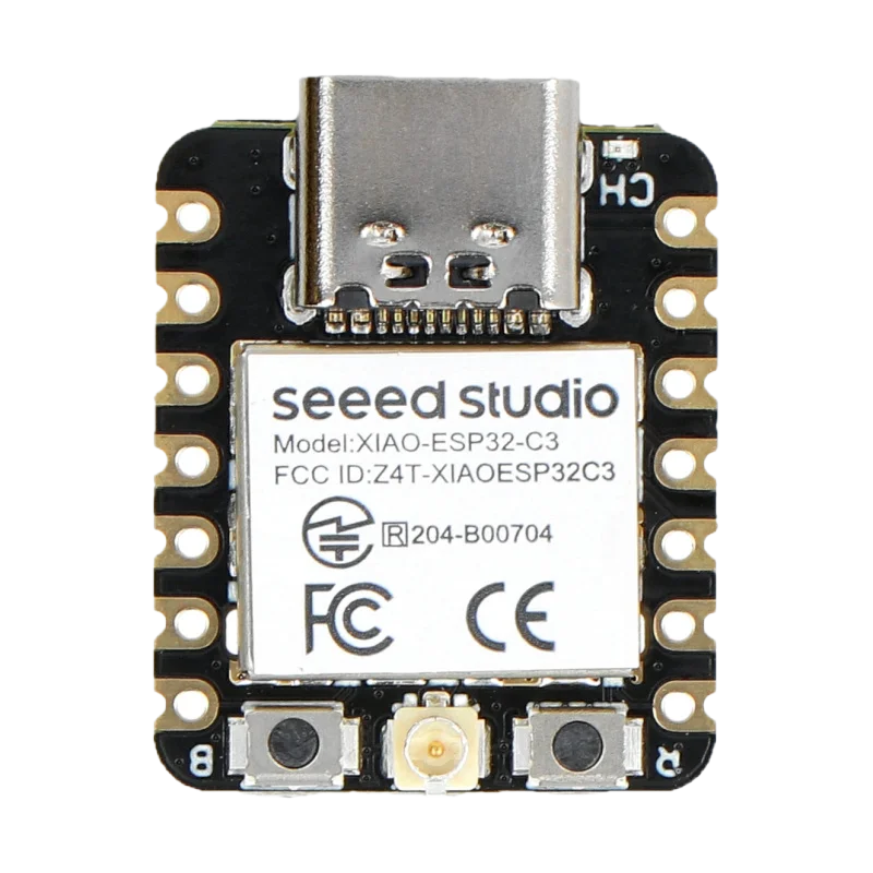
The Seeed Studio XIAO ESP32-C3 is the brain of the uFerris board:
- Architecture: 32-bit RISC-V (single core, 160 MHz)
- Memory: 400 KB SRAM, 4 MB Flash
- Connectivity: WiFi 802.11 b/g/n, Bluetooth 5 (LE)
- Peripherals: GPIO, I2C, SPI, UART, ADC, PWM
- USB: Native USB-C (no external programmer needed)
- Power: USB-C powered, 3.3V logic
Why uFerris?
- Zero wiring - all sensors and peripherals are pre-connected on the PCB
- Consistent setup - every participant has the same hardware, so we can focus on software
- Rich peripheral set - GPIO, I2C, and more ready to explore from minute one
- Designed for learning - pin labels, clear silk screen, and documentation all matched to the workshop exercises
Fallback: Wokwi Simulation
If you have hardware issues during the workshop, a Wokwi simulation is available. See the Wokwi Setup page for instructions.
Prerequisites
- Rust toolchain with
espflashinstalled (see Setup Guide) - Basic Rust knowledge: variables, functions, structs, ownership
- Curiosity about embedded systems
Workshop by Omar Hiari - The Embedded Rustacean
Rust Week 2026 · Utrecht, Netherlands
Pre-Workshop Setup
~30 min at home
Please complete this setup before the workshop day. Our goal is zero time spent on toolchain issues during the workshop itself.
If you run into problems, reach out to hi@theembeddedrustacean.com with subject "RW2026: Workshop Setup Help" - I'll help you get sorted before May 18.
⚠ Do This Before the Workshop
There will be no time to debug setup issues during the workshop. If you arrive without a working setup, please use the Wokwi fallback so you can follow along. A native setup is strongly recommended — get it done ahead of time.
What You'll Set Up
In the upcoming pages you will install/setup the following:
- Rust toolchain with the RISC-V target for ESP32-C3
- espflash for flashing firmware to the board
- esp-generate for creating new projects
- A test flash to verify everything works end-to-end
- Wokwi (optional) as a simulation fallback
Quick Check
Already set up? Run this to verify:
rustup target list --installed | grep riscv32imc
espflash --version
If both commands produce output, you're probably good. Jump to Hardware Verification to confirm with a real flash.
Rust Toolchain Setup
This guide assumes you have VS Code installed as your editor.
1. Install Rust
If you don't have Rust installed yet:
curl --proto '=https' --tlsv1.2 -sSf https://sh.rustup.rs | sh
Follow the prompts and accept the defaults. After installation, restart your terminal or run:
source $HOME/.cargo/env
Verify:
rustc --version
cargo --version
2. Add the RISC-V Target
The ESP32-C3 uses a RISC-V architecture. Add the target:
rustup target add riscv32imc-unknown-none-elf
3. Install espflash
espflash is used to flash firmware to ESP32 chips and monitor serial output:
cargo install espflash
This may take a few minutes to compile. Verify:
espflash --version
4. Install esp-generate
esp-generate creates new ESP32 Rust projects from templates:
cargo install esp-generate --locked
5. Generate a Test Project
Let's make sure everything works together:
esp-generate --chip esp32c3 -o unstable-hal -o vscode -o esp-backtrace -o log --headless hello_uferris
cd hello_uferris
The project should generate without errors.
6. Build the Test Project
cargo build --release
This first build will take a while as it downloads and compiles dependencies. Subsequent builds are fast.
Checkpoint: If
cargo build --releasecompletes without errors, your toolchain is ready. Next: Hardware Verification.
Troubleshooting
cargo install is slow
This is normal for the first install - Rust compiles from source. Grab a coffee.
Target not found
Make sure you're using a recent rustup:
rustup self update
rustup update
rustup target add riscv32imc-unknown-none-elf
Permission errors on Linux
You may need to add your user to the dialout group for serial port access (this matters for the next step):
sudo usermod -a -G dialout $USER
Log out and back in for this to take effect.
Hardware Verification
Now let's make sure your computer can talk to the ESP32-C3.
1. Open the Project in VS Code
Open the test project you generated in the previous step:
code hello_uferris
2. Connect the Board
Plug the ESP32-C3 Xiao into the uFerris Megalops Baseboard (if not already), then connect the baseboard to your computer via USB-C.
3. Build, Flash, and Monitor
Open a terminal in VS Code (Terminal → New Terminal) and run:
cargo run
You should see the project build, flash to the board, and then serial output from the ESP32-C3. Press Ctrl+C to exit the monitor.
Checkpoint: If you see serial output, your hardware setup is complete! You're ready for the workshop.
Troubleshooting
espflash can't find the serial port
If espflash fails to auto-detect your board, check that the device is recognized:
Linux:
ls /dev/ttyACM* /dev/ttyUSB* 2>/dev/null
macOS:
ls /dev/cu.usbmodem* /dev/cu.usbserial* 2>/dev/null
Windows (PowerShell):
Get-WMIObject Win32_SerialPort | Select-Object Name, DeviceID
If no device appears, see below.
No serial device found
Linux - udev rules:
Create a file /etc/udev/rules.d/99-esp32.rules:
SUBSYSTEMS=="usb", ATTRS{idVendor}=="303a", ATTRS{idProduct}=="1001", MODE="0666"
Then reload:
sudo udevadm control --reload-rules
sudo udevadm trigger
macOS - driver issues: The ESP32-C3 uses a built-in USB-JTAG interface. If it's not recognized, try a different USB cable (some cables are charge-only, without data lines).
Windows - driver: Install the USB-JTAG driver if the device isn't recognized.
Permission denied on Linux
sudo usermod -a -G dialout $USER
Log out and back in.
Board not responding
- Try a different USB cable (must support data, not just charging)
- Try a different USB port
- Press and hold the BOOT button on the ESP32-C3, then press RESET, then release BOOT - this forces download mode
- If all else fails, use the Wokwi fallback
Wokwi Fallback
The workshop is designed for real hardware — that's the experience. Use this fallback only if your hardware setup fails and you can't resolve it before the workshop.
GitHub Codespace with Wokwi
The easiest way to get a working simulation environment is to use the Simplified Embedded Rust book project, which includes a pre-configured devcontainer with Wokwi support for the ESP32-C3.
Steps
- Go to the Simplified Embedded Rust book project branch
- Click Code → Codespaces → Create codespace on project
- Wait for the devcontainer to build (this includes the Rust toolchain and Wokwi extension)
- Replace the code in
src/main.rswith your workshop exercise code - Build and run in the Wokwi simulator
The Wokwi board definition in this repo simulates the ESP32-C3. Pin assignments may not exactly match the uFerris board — check the simulation diagram and adjust as needed.
Switching to Hardware
If your hardware issue gets resolved during the workshop, you can switch to real hardware at any time by simply flashing with espflash instead of running the simulator. The code is the same — only the deployment target changes.
Part 1: Lay of the Land
~60-75 min
Before we touch any hardware, we need to build a mental model. This part covers everything you need to understand before you start writing embedded Rust code. More importantly, it gives you a framework for learning anything new in the ecosystem after this workshop is over.
The Problem
Embedded Rust is exciting. The ecosystem is growing fast. But that growth creates a real challenge for learners:
- Tutorials go stale. APIs change. Examples that worked six months ago might not compile today.
- Examples cover one use case. A blinky tutorial shows you how to blink one LED on one pin. But what if you need a different pin? A different configuration? A different peripheral entirely?
- Device and HAL crates are often underdocumented. Newer crates may have minimal docs, incomplete examples, or no usage guide at all. You need to know how to extract what you need from the source and API surface.
- Copy-paste gets you started, but doesn't get you far. If you can only reproduce what someone else wrote, you're stuck the moment you need something slightly different.
Why Are You Here?
You're going to learn how to fish, not just eat fish.
After this workshop, you'll know how to:
- Navigate the embedded Rust ecosystem
- Read crate documentation effectively
- Adapt examples to different boards and use cases
What I'm Going to Teach You
A mental model:
Instantiate → Configure → Control
And how to find the answers in the docs when nobody wrote a tutorial for your exact use case.
Let's start with the ecosystem.
Embedded Rust Development
~10 min
Embedded Development Options
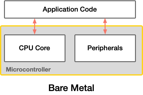
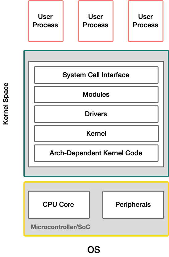
Bare Metal — Direct hardware access with no OS. Maximum determinism and minimal overhead, but you manage everything yourself. Best for simple, resource-constrained, or timing-critical applications.
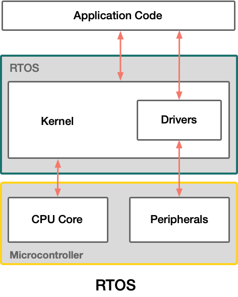
RTOS — A lightweight real-time operating system provides task scheduling and timing guarantees. Adds some overhead but enables multitasking with predictable behavior. Suited for applications requiring multiple concurrent tasks with real-time constraints.
Embedded OS — A full operating system (e.g., Linux) running on the device. Highest overhead and lowest determinism, but provides rich functionality (networking, filesystems, drivers). Requires more capable hardware.
In this workshop, we'll be doing bare metal Rust.
Development with the Standard Library
Vec<T> and Option<T>, library-defined operations on language primitives, standard macros, I/O and multithreading, among many other things."
Source: https://doc.rust-lang.org/std/
"Out of the Box" Rust is based on the Standard Library. It depends on system primitives provided by the OS system interface to implement functionality. It provides a runtime that sets up stack overflow protection, processes command-line arguments, and spawns the main thread. RTOS and Embedded OS can support it, but not bare metal.
Development with the Core Library
The core library is minimal: it isn't even aware of heap allocation, nor does it provide concurrency or I/O. These things require platform integration, and this library is platform-agnostic."
Source: https://doc.rust-lang.org/core/
The Core Library is a platform-agnostic subset of the Standard Library. It makes no assumptions about the underlying system and is necessary for bare metal implementations.
ESP supports both approaches. The std approach relies on the ESP-IDF framework, which has an underlying RTOS, through the esp-idf-hal crate — note that this is community supported only. In this workshop, we will be doing core (bare metal) development using the esp-hal, which is officially supported by Espressif.
Embedded Abstractions
~20 min
A Generic Peripheral Abstraction
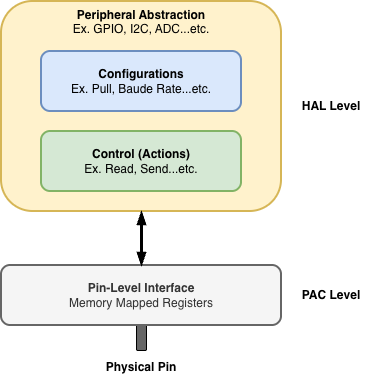
A peripheral abstraction, once created, needs methods to configure it and control it. The PAC provides memory-mapped interfaces for different peripherals to control pins — but this requires low-level knowledge and datasheet access. HALs take in the PAC abstractions and wrap them with user-friendly methods to perform the same operations without needing to manipulate registers. Note that this removes the need for datasheets to look at control and configuration specifics, but not the knowledge of how a peripheral works. You may still need to refer to a datasheet to understand certain properties of a peripheral for a particular controller.
The Full Rust "no-std" Stack
As shown in the figure below, the Rust no-std stack can comprise even more layers beyond just the PAC and HAL. Let's walk through each layer.
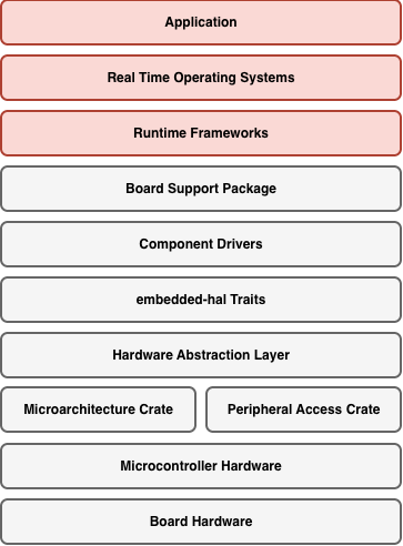
Micro Architecture Crate
Provides low-level access to CPU-specific features: interrupt handling, system timer, core registers. For RISC-V (ESP32-C3), this is the riscv crate.
Not something you interact with directly in most application code, but it's the foundation everything else builds on.
#![allow(unused)]
fn main() {
// Example: enabling interrupts at the CPU level
unsafe { riscv::interrupt::enable() };
}
The Peripheral Access Crate
Auto-generated from SVD files. A Rust representation of every register in the chip. Type-safe but low-level. You can use it directly, but you almost never need to.
For ESP32-C3: the esp32c3 crate.
#![allow(unused)]
fn main() {
// PAC-level: writing directly to a register
peripherals.GPIO.out_w1ts
    .write(|w| unsafe { w.bits(1 << 5) });
}
The Hardware Abstraction Layer
Safe, ergonomic Rust APIs on top of the PAC. This is where we'll spend most of our time. For ESP32 chips: esp-hal.
Provides the Instantiate → Configure → Control pattern for every peripheral.
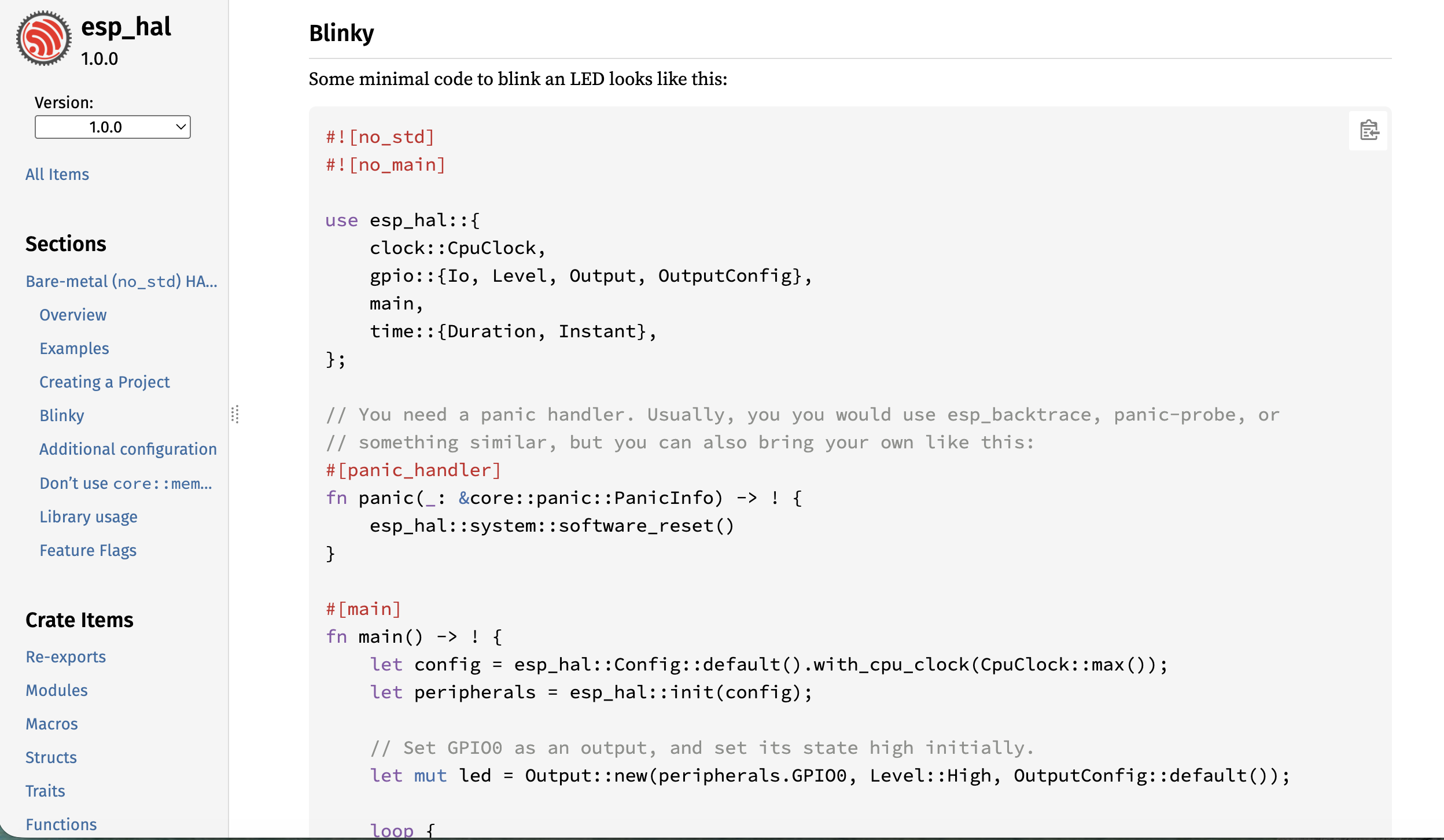
#![allow(unused)]
fn main() {
// HAL-level: safe, readable, type-checked
let mut led = Output::new(
    peripherals.GPIO5,
    Level::Low,
    OutputConfig::default(),
);
led.set_high();
}
embedded-hal Traits
The key to portability. These traits define a standard interface that any HAL can implement.
This is the contract between HALs and driver crates.
#![allow(unused)]
fn main() {
// Works on ANY microcontroller
fn blink(
    pin: &mut impl OutputPin,
    delay: &mut impl DelayNs,
) {
    pin.set_high().unwrap();
    delay.delay_ms(500);
    pin.set_low().unwrap();
    delay.delay_ms(500);
}
}
Driver Crates
Built on top of embedded-hal traits. A driver crate provides a high-level API for a specific sensor or device. Ideally drivers would all use embedded-hal traits but they don't need to. A driver that does use the traits though, is what makes it hardware-agnostic.
#![allow(unused)]
fn main() {
// This driver doesn't know about ESP32.
// It just needs something that implements I2c.
let mut imu = Icm42670::new(
    i2c, Address::Primary,
);
let accel = imu.accel_norm().unwrap();
}
Board Support Packages
The highest layer. Pre-configures everything for a specific board: pin assignments, peripheral setup, default configurations. Instead of remembering pin numbers, you use meaningful names.
#![allow(unused)]
fn main() {
// Without BSP:
let led = Output::new(
    peripherals.GPIO5,
    Level::Low,
    OutputConfig::default(),
);

// With BSP: the board knows
let led = board.led();
}
Embedded Patterns
~15 min
Mental Model
Embedded Development All Follows a Similar Pattern
Instantiate → Configure → Control
We will adopt this as a Mental Model to navigate the Rust Ecosystem
Peripheral Singletons
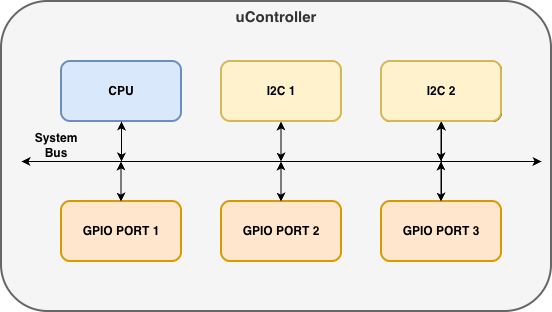
The singleton pattern ensures that only one instance of each peripheral exists in your program. In a microcontroller, there is physically a single block for each peripheral — the software gives us access to only that one instance, not duplicates or copies of it.
At the PAC level, we use Peripherals::take() to claim ownership of all peripherals at once. This can only be called once — calling it again returns None. This guarantees exclusive access.
#![allow(unused)]
fn main() {
let peripherals = Peripherals::take().unwrap();
}
From that single call, we can access individual peripherals (one instance per block). We then use these PAC instances to create HAL-level driver instances, as shown below.
GPIO Instantiation Examples
Although the methods differ between HALs, they are all doing the same thing — taking a peripheral singleton and creating a GPIO output driver instance:
rp2040-hal
#![allow(unused)]
fn main() {
let pac = pac::Peripherals::take()
    .unwrap();
let sio = Sio::new(pac.SIO);
let pins = Pins::new(
    pac.IO_BANK0,
    pac.PADS_BANK0,
    sio.gpio_bank0,
    &mut pac.RESETS,
);
let led = pins.gpio25
    .into_push_pull_output();
}
esp-hal
#![allow(unused)]
fn main() {
let peripherals = esp_hal::init(
    Config::default()
);
let led = Output::new(
    peripherals.GPIO0,
    Level::High,
    OutputConfig::default(),
);
}
stm32f4xx-hal
#![allow(unused)]
fn main() {
let pac = Peripherals::take()
    .unwrap();
let gpioa = pac.GPIOA.split();
let led = gpioa.pa5
    .into_push_pull_output();
}
Configure
Once we have an instance, it gives us methods to configure it. Again, although the API style varies across HALs, they are all configuring a GPIO input with a pull-up resistor:
rp2040-hal
#![allow(unused)]
fn main() {
let button = pins.gpio15
    .into_pull_up_input();
}
esp-hal
#![allow(unused)]
fn main() {
let button = Input::new(
    peripherals.GPIO9,
    InputConfig::default()
        .with_pull(Pull::Up),
);
}
stm32f4xx-hal
#![allow(unused)]
fn main() {
let button = gpioa.pa0
    .into_pull_up_input();
}
Control
And finally, the instance provides methods to control the peripheral. All three HALs are checking if a button is pressed and setting an LED high — the syntax is nearly identical:
rp2040-hal
#![allow(unused)]
fn main() {
if button.is_high().unwrap() {
    led.set_high().unwrap();
}
}
esp-hal
#![allow(unused)]
fn main() {
if button.is_high() {
    led.set_high();
}
}
stm32f4xx-hal
#![allow(unused)]
fn main() {
if button.is_high() {
    led.set_high();
}
}
Things to Note
-
HAL Peripheral instances are drivers for microcontroller peripheral blocks
-
Off-controller device drivers (e.g. an I2C sensor) are a similar concept. They are instances that use microcontroller peripheral drivers to provide abstraction. Same concept as how peripherals use the PAC.
-
Configuration is sometimes passed as an argument to the instantiation statement rather than as a separate step
-
HALs often implement embedded-hal traits to provide device drivers with a common interface across controllers
Navigating Documentation
~15 min
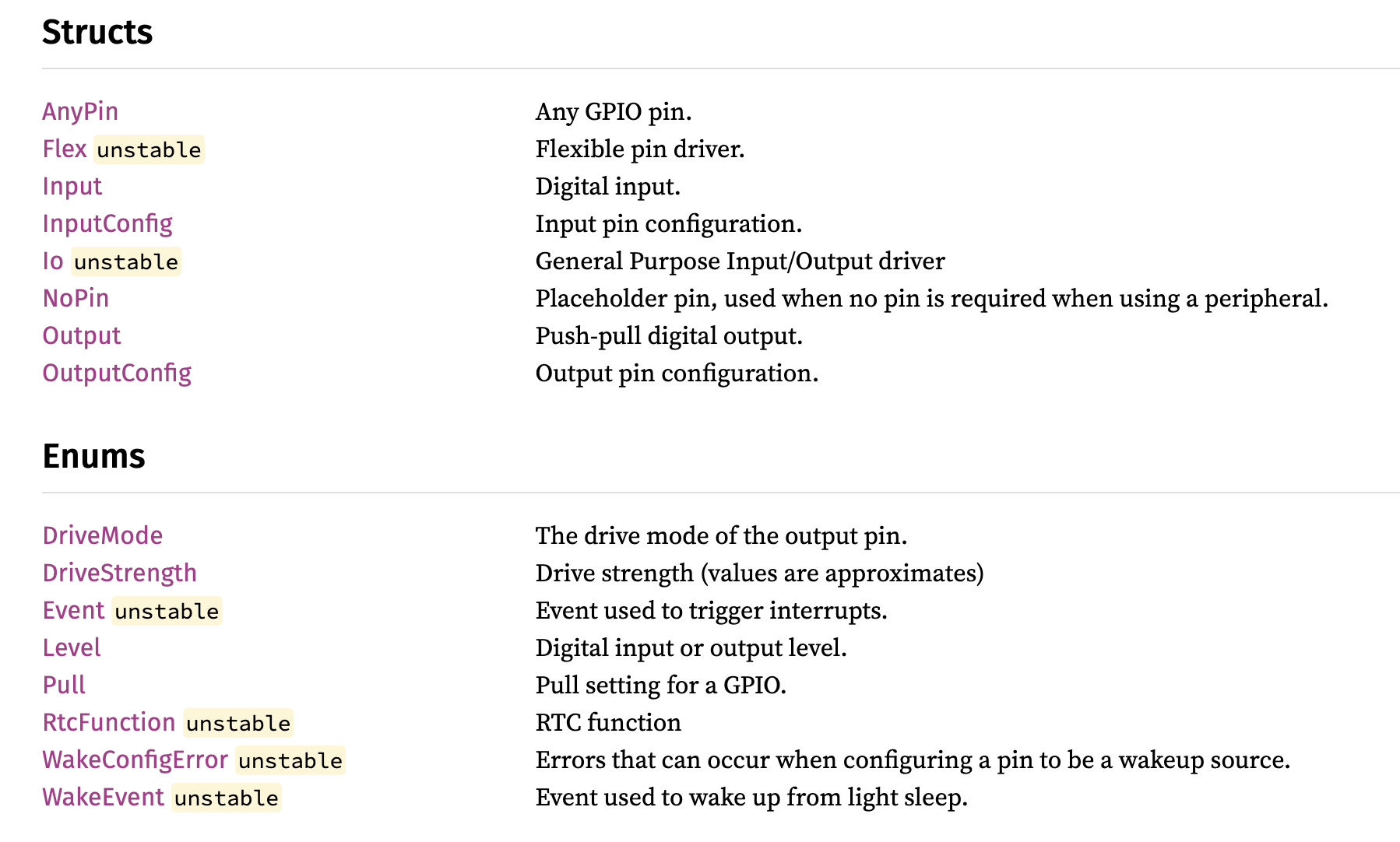
Navigate to the Peripheral Module
Each peripheral typically gets its own module in a HAL crate. You can find the module list by navigating to the bottom of the crate's documentation page.
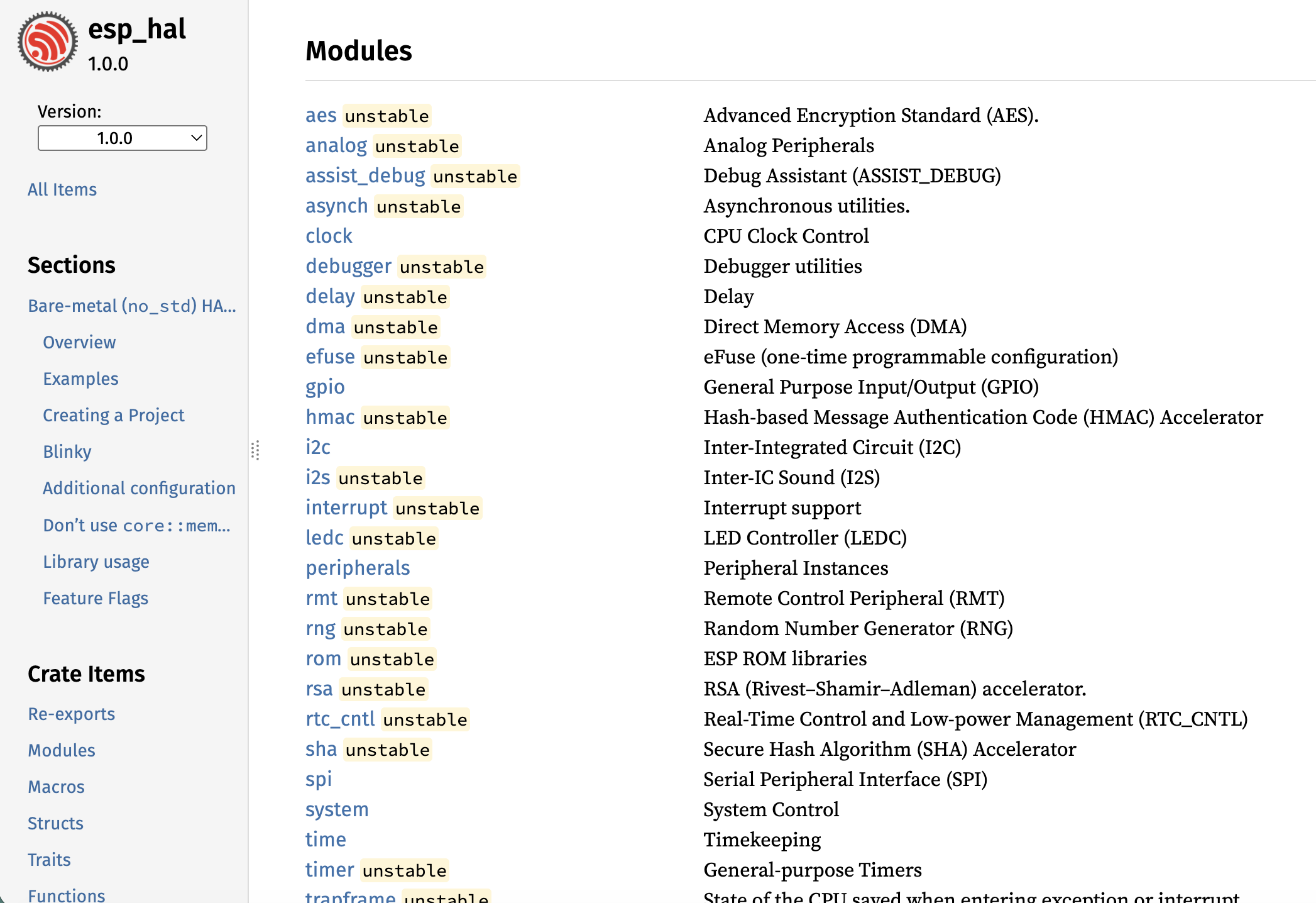
Find an Example for Your Peripheral
Simple examples are often shown directly in the module documentation. Most HAL repos also have a dedicated examples directory that you can browse on GitHub.
Identify the Peripheral Driver Struct
Use the example to apply the mental model. Identify the driver struct and how it is instantiated, configured, and controlled.
Access the Driver Struct
Once you have identified the driver struct, navigate to its documentation page. There you will find the configuration and control methods available to you.
Part 2: GPIO
~60-75 min
Time to get hands-on. In this module, you'll apply the Instantiate → Configure → Control pattern to GPIO - the most fundamental peripheral on any microcontroller.
You'll start with a live demo walkthrough, then use the documentation to navigate and adapt examples on your own.
What You'll Do
- Exercise A: Blinky - find the blinky example in esp-hal docs, adapt it to the uFerris LED pin
- Exercise B: Button Input - find the Input abstraction, configure pull-up, detect a button press
- Exercise C: Alternative Blink - find a different way to achieve the same blink behavior, without using the same approach as Exercise A
- Cross-HAL Comparison - inspect how rp2040-hal and stm32f4xx-hal handle the same GPIO tasks
GPIO Foundations
~10 min slides
What is GPIO?
General Purpose Input/Output
Standard digital interface to the outer world. The most basic peripheral: making pins go high or low, and reading whether they're high or low.
Configurations: Direction
- Output — you drive the pin (e.g., turn on an LED)
- Input — you read the pin (e.g., detect a button press)
Configurations: Output
Modes
- Push-pull (typically default) — actively drives the pin high and low
- Open-drain — actively drives low, but floats when "high" (needs external pull-up)
Drive Strength
How much current the pin can source or sink. Higher drive strength = brighter LED, but more power consumption.
Configurations: Input
Internal Pull Resistor
- Pull-up — pin reads high when nothing is connected; button pulls it low
- Pull-down — pin reads low when nothing is connected; button pulls it high
- Floating — no pull resistor; pin state is undefined when nothing is connected
GPIO Exercises
~50 min
Exercise A: Blinky
- Find the blinky example in the esp-hal GPIO documentation
- Identify the Instantiate, Configure, and Control steps
- Adapt the pin to match the uFerris LED pin (check your pinout card)
- Flash and verify — the LED should blink
Exercise B: Button Input
- Find the Input abstraction in the esp-hal GPIO documentation
- Configure it with pull-up (since the hardware button pulls to ground)
- Find the method that detects when the button is pressed (low)
- Modify your blinky to turn on the LED when the button is pressed
Exercise C: Alternative Blink
- Look into the Output documentation in esp-hal
- Find a different way to achieve the same blink behavior, without using the same approach as in Exercise A
- Modify your code to blink the LED using this alternative approach
Cross-HAL Comparison
How do other HALs handle GPIO? Navigate the documentation for these two libraries and find how they approach the same tasks:
Compare how each HAL handles Instantiate, Configure, and Control for GPIO.
Exercise A: Blinky
~15 min
Goal
Get an LED blinking on the uFerris board by finding and adapting an existing example from the esp-hal documentation.
Steps
1. Create a New Project
esp-generate --chip esp32c3 -o unstable-hal -o vscode -o esp-backtrace -o log --headless gpio_blinky
cd gpio_blinky
2. Find the Example
Navigate to the esp-hal GPIO documentation.
Look for a blinky example — check:
- The module-level documentation (
esp_hal::gpio) - The
Outputstruct page - The esp-hal examples directory on GitHub
3. Apply the Mental Model
Read the example and identify:
- Instantiate — How is the
Outputcreated? What arguments does it take? - Configure — What configuration is applied? (Level, OutputConfig)
- Control — What method is used to change the LED state?
4. Adapt to uFerris
- Check your pinout card for the LED pin on the uFerris board
- Update the GPIO pin in the example to match
- Make sure the initial level matches your hardware (active high or active low?)
5. Build and Flash
cargo build --release
espflash flash target/riscv32imc-unknown-none-elf/release/blinky --monitor
Verify: the LED should blink at a steady rate.
What to Notice
- The
Output::new()call combines Instantiate and Configure in one statement - Look at what other methods
Outputprovides besides the one used in the example
Exercise B: Button Input
~20 min
Goal
Read a physical button press and use it to control the LED. You'll need to find the Input abstraction and configure it correctly for the uFerris hardware.
Steps
1. Create a New Project
esp-generate --chip esp32c3 -o unstable-hal -o vscode -o esp-backtrace -o log --headless gpio_button
cd gpio_button
2. Find the Input Abstraction
Navigate to the esp-hal GPIO documentation.
- Find the
Inputstruct - Read what arguments its constructor takes
- Look at what configuration options are available
3. Understand the Hardware
The uFerris button is wired to pull the pin to ground when pressed:
- When not pressed: pin floats (needs pull-up to read high)
- When pressed: pin is pulled low
This means you need:
- Pull-up resistor configuration (internal)
- Detect a low level to know the button is pressed
4. Configure the Input
Apply the mental model:
- Instantiate — Create an
Inputinstance for the button pin - Configure — Set the pull resistor to pull-up
Check the InputConfig struct and its methods. How do you set the pull direction?
5. Read the Button and Control the LED
Find the method on Input that lets you read the current pin state. Use it to:
- Detect when the button is pressed (low)
- Turn on the LED when pressed
- Turn off the LED when released
6. Build and Flash
cargo build --release
espflash flash target/riscv32imc-unknown-none-elf/release/button --monitor
What to Notice
- How does
Inputconfiguration compare toOutputconfiguration? - The
Inputstruct has multiple methods for reading state
Exercise C: Alternative Blink
~15 min
Goal
Find a different way to achieve the same blink behavior, without using the same approach as in Exercise A.
Steps
1. Create a New Project
esp-generate --chip esp32c3 -o unstable-hal -o vscode -o esp-backtrace -o log --headless gpio_challenge
cd gpio_challenge
2. Explore the Output Documentation
Go back to the Output struct documentation and scroll through all the methods available on Output.
3. Find an Alternative
The blinky example in Exercise A used one specific approach to switch the LED on and off. Your task: find a different method that achieves the same result.
Hints:
- There's more than one way to change pin state
- Some methods combine multiple operations
- Check both the inherent methods and the trait methods
4. Modify and Test
Update your blinky code to use the alternative approach. The LED should still blink at the same rate.
cargo build --release
espflash flash target/riscv32imc-unknown-none-elf/release/blinky --monitor
What to Notice
- How many different ways can you find to control an output pin?
- Which approach results in simpler code?
Part 3: I2C
~60-75 min
In this module, you'll move beyond GPIO to a communication protocol — I2C.
What You'll Do
- Exercise A: Bus Scan - set up an I2C bus on the uFerris board and discover what devices are connected
- Exercise B: GPIO over I2C - use the TCA6424 I/O expander to control GPIO pins over I2C, replicating what you did with direct GPIO
- Exercise C: Adaptation Challenge - read a button input through the I/O expander, controlling an LED entirely over I2C
- Cross-HAL Comparison - inspect how rp2040-hal and stm32f4xx-hal handle I2C
I2C Foundations
~10 min slides
What is I2C?
I2C (or IIC) stands for Inter-Integrated Circuit. It is a two-wire bus protocol for communicating with sensors, displays, and other devices.
The two wires are:
- SDA — Serial Data (bidirectional). Used to propagate data bits.
- SCL — Serial Clock (driven by the controller). Used to propagate a clock to synchronize data exchanges on the bus.
Since it is a bus, multiple devices can share the same two wires. Each device has a unique address (7-bit) that the controller (master) can use to address any other device (slave) on the same bus.
Theory of Operation

- Each bus has at least one master and one or more slaves that it communicates with. The master is the entity that orchestrates operations on the bus.
- Typically, the microcontroller we are programming would be the master. The master addresses the slaves using the 7-bit address.
- The exchange speed of the data is governed by the clock speed (propagated on the SCL line).
- A master can perform two operations: either read or write.
- I2C exchanges data in one-byte chunks.
Write Operations
A master writes data to a slave. You need to provide:
- The address of the slave
- An array of bytes that need to be written
Read Operations
A master reads data from a slave. You need to provide:
- The address of the slave
- A byte array buffer for the received data
Configurations
| Setting | Description |
|---|---|
| Clock frequency | 100 kHz (standard), 400 kHz (fast), or custom |
| SDA/SCL pins | Any GPIO with I2C capability |
I2C Exercises
~55 min
uFerris uses an I/O expander. An I/O expander is used to expand the number of GPIO pins on a controller. The expander communicates over I2C to configure and control GPIO pins. This means we can get many more GPIO using only two I2C lines!
The expander used is the TCA6424, and the first exercise would be to find out its address.
Exercise A: Bus Scan
- Find a ready I2C example in the esp-hal I2C documentation
- Identify the Instantiate, Configure, and Control steps
- Adapt the pins to match the uFerris board (check your pinout card for SDA and SCL)
- Scan all addresses (0x01–0x7F) by attempting a write to each — note which devices respond
Exercise B: GPIO over I2C
The uFerris board uses a TCA6424 I/O expander — its address should have appeared when scanning in Exercise A.
- Configure a pin on the I/O expander as output
- Blink an LED connected to the I/O expander
Exercise C: Adaptation Challenge
- Configure a pin on the I/O expander as input
- Read the button state through the I/O expander
- Use it to control the LED — same logic as the GPIO exercise, but entirely over I2C
Cross-HAL Comparison
How do other HALs handle I2C? Navigate the documentation for these two libraries and find how they approach the same tasks:
Compare how each HAL handles Instantiate, Configure, and Control for I2C.
Exercise A: Bus Scan
~15 min
Goal
Set up an I2C bus on the uFerris board and scan for connected devices.
Steps
1. Create a New Project
esp-generate --chip esp32c3 -o unstable-hal -o vscode -o esp-backtrace -o log --headless i2c_scan
cd i2c_scan
2. Find an I2C Example
Navigate to the esp-hal I2C documentation.
Look for an I2C example in:
- The module-level documentation (
esp_hal::i2c) - The
I2cstruct page - The esp-hal examples directory on GitHub
3. Apply the Mental Model
Read the example and identify:
- Instantiate — How is the
I2ccreated? What peripheral and pins does it need? - Configure — What configuration is applied? (Clock speed, pins)
- Control — What methods are available for reading/writing?
4. Adapt to uFerris
- Check your pinout card for the I2C SDA and SCL pins
- Update the pins in the example to match the uFerris board
5. Scan the Bus
Write a loop that attempts to communicate with every address from 0x01 to 0x7F:
- For each address, try a zero-length write
- If the write succeeds, a device is present at that address
- Print the address of each device found
6. Build and Flash
cargo build --release
espflash flash target/riscv32imc-unknown-none-elf/release/i2c-scan --monitor
What to Notice
- Which addresses respond? Write them down — you'll need them in the next exercise
- One of those addresses is the TCA6424 I/O expander
- Compare the I2C
Instantiatepattern to GPIO — what's similar? What's different?
Exercise B: GPIO over I2C
~25 min
Goal
Use the TCA6424A I/O expander on the uFerris board to control GPIO pins over I2C. This replicates what you did with direct GPIO — but through an I2C device.
Background
The TCA6424A is a 24-bit I/O expander connected via I2C. It provides three banks (ports) of 8 GPIO pins each (P0, P1, P2), giving you 24 additional GPIO pins over just two I2C wires. Its address should have appeared when you scanned the bus in Exercise A.
How I2C Communication Works with the TCA6424A
To interact with the I/O expander, communication happens in two cycles:
- First cycle (write): You send the register address you want to access — this tells the device which internal register you want to read from or write to.
- Second cycle (read or write): You either write a value to that register (to configure or control a pin) or read back the current value.
For a write operation, you send the register address followed by the data byte in the same I2C write transaction.
For a read operation, you first write the register address, then perform a separate I2C read to get the data back.
TCA6424A Register Map
| Register | Port 0 | Port 1 | Port 2 | Purpose |
|---|---|---|---|---|
| Input | 0x00 | 0x01 | 0x02 | Read pin levels |
| Output | 0x04 | 0x05 | 0x06 | Set output pin levels |
| Configuration | 0x0C | 0x0D | 0x0E | Set pin direction: 0 = output, 1 = input (default) |
Steps
1. Create a New Project
esp-generate --chip esp32c3 -o unstable-hal -o vscode -o esp-backtrace -o log --headless i2c_expander
cd i2c_expander
2. Configure Pin Direction
To use a pin as output, you need to write to the Configuration register for the appropriate port. Set the corresponding bit to 0 for output. Find the I2C abstraction in esp-hal that lets you write to a device at a specific address.
3. Set a Pin High
To turn on an LED, write to the Output register for the appropriate port. Set the corresponding bit to 1 for high. Use the same I2C write approach.
4. Blink an LED
Combine the above in a loop to blink an LED connected to the I/O expander:
- Configure the port direction as output (once at startup)
- In a loop: set the pin high, delay, set the pin low, delay
5. Build and Flash
cargo build --release
espflash flash target/riscv32imc-unknown-none-elf/release/i2c-expander --monitor
What to Notice
- Compare the complexity of GPIO-over-I2C vs direct GPIO — what's the tradeoff?
Exercise C: Adaptation Challenge
~15 min
Goal
Extend your I/O expander setup to read a button input over I2C — replicating the GPIO button exercise, but entirely through the I2C I/O expander.
Steps
1. Create a New Project
esp-generate --chip esp32c3 -o unstable-hal -o vscode -o esp-backtrace -o log --headless i2c_challenge
cd i2c_challenge
2. Configure an Input Pin
Using the TCA6424 registers:
- Set a pin's configuration bit to
1(input) - This pin should be connected to a button on the uFerris board
3. Read the Button State
- Read the input register for the relevant bank
- Check the bit corresponding to your input pin
- Detect when the button is pressed
4. Control the LED
Combine input reading with output control:
- Read the button state from the I/O expander
- When pressed, turn on the LED (on the I/O expander)
- When released, turn off the LED
5. Build and Flash
cargo build --release
espflash flash target/riscv32imc-unknown-none-elf/release/i2c-button --monitor
What to Notice
- The logic is identical to the direct GPIO exercise — only the hardware interface changed
- All communication goes through I2C read/write operations
- Think about latency: how does I2C polling compare to direct GPIO polling?
- Could you use interrupts with the I/O expander? (The TCA6424 has an INT pin)
Part 4: Interrupts
~45-60 min
So far, all your code has been polling - checking the button state in a loop, reading sensors repeatedly. This works, but it's wasteful. The CPU spins constantly even when nothing is happening.
Interrupts let the hardware notify your code when something happens. The CPU can do other work (or sleep) until an event occurs.
What You'll Do
- Interrupt-driven button - configure the existing GPIO input button example to use interrupts instead of polling
- I/O Expander interrupt - use the TCA6424's INT output to detect input changes without polling over I2C
Interrupts
~15 min
Polling vs Interrupts
Polling
With polling, the CPU constantly checks the state of a peripheral in a loop. This is simple to implement but wastes CPU cycles — the processor is busy-waiting even when nothing is happening.
#![allow(unused)]
fn main() {
loop {
    if button.is_low() {
        // react to button press
    }
    // CPU is busy-waiting here, doing nothing useful
}
}
Interrupts
With interrupts, the hardware notifies the CPU when an event occurs. The CPU can sleep or do other work in the meantime, only waking when needed. This is more efficient but requires additional setup.
#![allow(unused)]
fn main() {
loop {
    // CPU can sleep or do other work
    // it is idle until an event occurs
}

// Hardware triggers this handler automatically
#[handler]
fn gpio_handler() {
    // react to the event
}
}
Components of Interrupt Code
Interrupt code is formed of three components:
- Global Shared Data — Any data that needs to be shared between the main thread and the interrupt handler
- Interrupt Setup — Configuring the interrupt per peripheral (what event to listen for, enabling it, moving data to shared state)
- Interrupt Service Routine (ISR) — The code that reacts to the interrupt event
// 1. Global Shared Data
static SHARED: Mutex<RefCell<Option<Input>>> =
    Mutex::new(RefCell::new(None));

fn main() {
    // ... peripheral setup ...

    // 2. Interrupt Setup
    button.listen(Event::FallingEdge);
    critical_section::with(|cs| {
        SHARED.borrow_ref_mut(cs).replace(button);
    });
}

// 3. Interrupt Service Routine
#[handler]
fn gpio_handler() {
    critical_section::with(|cs| {
        // handle event, clear interrupt
    });
}
Setup Happens in the Configure Stage
Setup entails three steps:
-
Configuring the interrupt — What do we want to listen to?
- Edge events (rising, falling, any)
- Level events (high, low)
-
Enabling the interrupt — Allowing the interrupt events to go through
- Peripheral-level enable
- Interrupt controller enable
-
Configuring global shared data — Setting up shared state
Mutex<RefCell<Option<T>>>pattern- Moving peripherals into global statics via
critical_section
Interrupt Exercises
~30 min
Exercise A: GPIO Interrupts
Configure the existing GPIO input button example to use interrupts instead of polling.
- Check the
esp-halabstractions and code examples - See if you can find examples that you can adapt
- Apply the mental model: find the Instantiate, Configure, and Control steps for interrupt-driven GPIO
Exercise B: I/O Expander Interrupt
The TCA6424 I/O expander has an INT output connected to a Xiao GPIO pin. Use it to get notified of input changes instead of polling over I2C.
- Configure a GPIO interrupt on the INT pin
- When triggered, read the I/O expander over I2C to determine what changed
- This combines GPIO interrupts with I2C communication
Exercise A: Interrupt-Driven Button
~20 min
Goal
Configure the existing GPIO input button example from Part 2 to use interrupts instead of polling. Check the esp-hal abstractions and code examples to see if you can find any examples that you can adapt.
Steps
1. Create a New Project
esp-generate --chip esp32c3 -o unstable-hal -o vscode -o esp-backtrace -o log --headless gpio_interrupt
cd gpio_interrupt
2. Find Interrupt Examples
Search the GPIO Input documentation or the esp-hal examples directory for interrupt examples.
Look for how interrupts are set up — recall the three components from the slides:
- Interrupt Setup — configuring what event to listen for and enabling the interrupt
- Interrupt Service Routine — the code that reacts to the interrupt event
- Global Shared Data — any data shared between the main thread and the handler
3. Apply the Pattern
Convert your polling code to use interrupts:
- Configure the interrupt (what event do you want to listen to?)
- Enable the interrupt (allow events to go through)
- Set up global shared data (how will the handler communicate with the main loop?)
4. Build and Flash
cargo build --release
espflash flash target/riscv32imc-unknown-none-elf/release/interrupt-button --monitor
Press the button. The LED should toggle.
5. Explore Trigger Configurations
Look up the Event enum in esp-hal's GPIO module. What variants are available?
What to Notice
- The interrupt setup happens in the Configure stage
- You must always call
clear_interrupt()in the handler - Compare: what can the main loop do now that it couldn't when polling?
Exercise B: I/O Expander Interrupt
~15 min
The Challenge
The TCA6424 I/O expander on the uFerris board has an INT output pin that connects to one of the Xiao GPIO pins. Instead of polling the I/O expander over I2C to check for button presses, use this interrupt line to get notified when an input changes.
Steps
- Create a new project
esp-generate --chip esp32c3 -o unstable-hal -o vscode -o esp-backtrace -o log --headless expander_interrupt
cd expander_interrupt
-
Find the INT pin — check your pinout card to see which Xiao GPIO pin the I/O expander's INT output is connected to.
-
Configure a GPIO interrupt on that pin — the INT line is typically active-low, so configure for a falling edge trigger.
-
In the interrupt handler, set a flag indicating that the I/O expander state has changed.
-
In the main loop, when the flag is set, read the I/O expander's input register over I2C to determine which button was pressed, then react accordingly (e.g., toggle an LED on the expander).
What to Notice
- This combines two peripherals: GPIO interrupts and I2C communication
- The interrupt tells you something changed, but you still need I2C to find out what changed
- Compare this to your earlier polling approach — what's the advantage?
- The Instantiate → Configure → Control pattern applies to both the GPIO interrupt setup and the I2C I/O expander
Part 5: The uFerris BSP (Bonus)
~20-30 min (if time permits)
You've now worked at the HAL level (GPIO, I2C with esp-hal) and used driver crates (I/O expander). There's one more layer in the stack: the Board Support Package.
A BSP allows us to skip the Configure step. The pattern becomes simply Instantiate → Control.
Same idea as HAL with PAC — BSP takes PAC singletons as input to create HAL instances and use them.
What You'll Do
- Redo earlier exercises using the BSP — repeat your GPIO and I2C exercises using the uFerris BSP instead of raw HAL calls
- Examine the adapter layer — look at how the ESP32-C3 adapter was created
What Is a BSP?
~5 min slides
The Top of the Stack
A Board Support Package encapsulates board-specific knowledge — pin assignments, peripheral configuration, and hardware defaults.
BSP allows us to skip the configure step. Pattern becomes Instantiate → Control.
Same idea as HAL with PAC — BSP takes PAC singletons as input to create HAL instances and use them.
Without BSP (raw HAL)
#![allow(unused)]
fn main() {
// Instantiate
let peripherals = esp_hal::init(Config::default());

// Configure
let led = Output::new(
    peripherals.GPIO5,
    Level::Low,
    OutputConfig::default(),
);

// Control
led.set_high();
}
With BSP
#![allow(unused)]
fn main() {
// Instantiate (BSP takes HAL peripherals as input)
let peripherals = esp_hal::init(Config::default());
let mut uferris = uferris_init(peripherals).unwrap();

// Control — no configure step needed
uferris.led1_on();
}
The BSP still requires instantiation — you pass the HAL peripherals into uferris_init(). But the board-specific configuration (which pin, what drive strength, which pull resistor) is all handled internally. You go straight from Instantiate to Control.
It's Not Magic
The BSP is just Rust code that does exactly what you've been doing — but packages it up with meaningful names. Open the source and you'll see Output::new(), I2c::new(), and all the same patterns.
The value is:
- No pin lookup errors — the board knows its own pin assignments
- Sensible defaults — configurations chosen for the specific board's hardware
- Convenience — less boilerplate for common setups
When to Use a BSP vs. Raw HAL
| Use BSP When | Use Raw HAL When |
|---|---|
| Quick prototyping | You need non-default configurations |
| Your board has a BSP | You're using custom hardware |
| You don't need fine control | You want to learn the lower layers |
In a workshop about ecosystem navigation, understanding the raw HAL is essential. The BSP is the reward: once you understand the layers underneath, you can appreciate what the BSP does for you.
BSP Exercises
~20 min
Exercise: Redo with the BSP
Repeat the earlier GPIO and I2C exercises using the uFerris BSP
- Redo blinky, button input, and I2C exercises using BSP abstractions instead of raw HAL
- Notice how the BSP skips the Configure step — pattern becomes Instantiate → Control
- Examine the adapter layer to see how it was created for the ESP32-C3
Exercise: Explore the uFerris BSP
~15-20 min
Goal
Redo your earlier exercises using the uFerris BSP instead of raw HAL calls. See how the BSP simplifies the Instantiate → Configure → Control pattern down to Instantiate → Control.
Steps
Step 1: Create a New Project
esp-generate --chip esp32c3 -o unstable-hal -o vscode -o esp-backtrace -o log --headless bsp_blinky
cd bsp_blinky
Step 2: Read the BSP Source
Open the uFerris BSP crate source code. Don't use it yet — just read it.
Answer these questions:
- How does the BSP map pin numbers to named functions?
- What configuration choices has the BSP author made? (Drive strength? Pull resistors? I2C speed?)
- Can you find the Instantiate → Configure → Control pattern inside the BSP code?
The BSP calls Output::new(), which calls into the HAL, which writes to PAC registers, which toggle actual hardware. Every layer you've learned is present — the BSP just wraps them up.
Step 3: Redo Blinky with BSP
Refactor your blinky exercise to use the BSP. You still need to instantiate the board, then get the LED from it. Notice how the pin number and configuration are no longer your concern.
Step 4: Redo Button Input with BSP
Refactor the button exercise. How does the BSP handle:
- Pin assignment?
- Pull-up configuration?
Step 5: Redo I2C with BSP
Refactor the I2C exercise. The BSP should provide a pre-configured I2C bus — no need to specify pins or clock speed.
Step 6: Examine the Adapter Layer
Look at the BSP source code for the ESP32-C3 adapter:
- How are HAL types mapped to board-level names?
- What abstractions does the adapter provide?
- Could you write an adapter for a different Xiao module?
What to Notice
- The BSP skips Configure — that's the whole point
- The pattern becomes simply Instantiate → Control
- Every layer builds on the one below it
Cheatsheet
uFerris Pinout Reference
| Signal Name | Xiao Pin | I/O Expander Pin | Direction | ESP32-C3 Pin |
|---|---|---|---|---|
| LED 1 | D1/A1 | - | Output | GPIO3 |
| LED 2 | - | P14 | Output | - |
| LED 3 | - | P15 | Output | - |
| Buzzer | D2/A2 | - | Output | GPIO4 |
| SW1 | - | P07 | Input | - |
| SW2 | - | P06 | Input | - |
| SW3 | - | P05 | Input | - |
| SW4 | - | P04 | Input | - |
| SW5 | D3 | - | Input | GPIO5 |
| SW6 Pos 1 | - | P16 | Input | - |
| SW6 Pos 2 | - | P17 | Input | - |
| SW7 Pos 1 | - | P00 | Input | - |
| SW7 Pos 2 | - | P01 | Input | - |
| SDA | D4 | - | Comms | GPIO6 |
| SCL | D5 | - | Comms | GPIO7 |
| LDR | D0/A0 | - | Analog | GPIO2 |
| Digit 1 | - | P10 | Output | - |
| Digit 2 | - | P11 | Output | - |
| Digit 3 | - | P12 | Output | - |
| Digit 4 | - | P13 | Output | - |
| Seg A | - | P20 | Output | - |
| Seg B | - | P21 | Output | - |
| Seg C | - | P22 | Output | - |
| Seg D | - | P23 | Output | - |
| Seg E | - | P24 | Output | - |
| Seg F | - | P25 | Output | - |
| Seg G | - | P27 | Output | - |
| DP | - | P26 | Output | - |
| XiaoTx | D6 | nINT | - | GPIO21 |
| XiaoMosi | D10 | - | - | GPIO10 |
| XiaoMiso | D9 | - | - | GPIO9 |
| XiaoScl | D8 | - | - | GPIO8 |
| XiaoRx | D7 | - | - | GPIO20 |
Install esp-generate
cargo install esp-generate --locked
Start a New Project
esp-generate --chip esp32c3 -o unstable-hal -o vscode -o esp-backtrace -o log --headless [project_name]
Useful Links
- ESP Rust Documentation: https://docs.espressif.com/projects/rust/
- uFerris BSP: https://github.com/uFerris-rs/uferris-bsp
- uFerris Hardware: https://github.com/uFerris-rs/uferris-hw
TCA6424A Register Reference
| Register | Port 0 | Port 1 | Port 2 | Purpose |
|---|---|---|---|---|
| Input | 0x00 | 0x01 | 0x02 | Read pin levels |
| Output | 0x04 | 0x05 | 0x06 | Set output pin levels |
| Configuration | 0x0C | 0x0D | 0x0E | Pin dir: 0=out, 1=in |
Wrap-Up & Next Steps
What You Learned Today
The Mental Model
Instantiate → Configure → Control - it works for every peripheral, every HAL, every driver crate.
| Step | What You Do | Where in the Docs |
|---|---|---|
| Instantiate | Create a driver instance | Struct page → new() or builder |
| Configure | Set behavior options | Config structs, enums |
| Control | Read/write/interact | Trait implementations, methods |
The Ecosystem Layers
BSP → Driver Crates → embedded-hal → HAL → PAC → Hardware
You know what each layer does and how to read its documentation.
The Skills
- Navigate crate documentation to find peripheral modules, examples, driver structs, and methods
- Apply the mental model across different HALs — you compared esp-hal, rp2040-hal, and stm32f4xx-hal
- Use the BSP layer to simplify the pattern to Instantiate → Control
The Workflow
Find a basic example → Apply the mental model → Map to documentation → Modify
The example shows ONE way. The docs show ALL ways. Your job is to explore.
Where to Go From Here
Keep Learning with uFerris
Your uFerris board has more peripherals to explore:
- SPI - faster serial communication (displays, SD cards)
- ADC - read analog values (potentiometers, light sensors)
- PWM - control LED brightness, servo motors
- ESP-NOW - wireless communication between ESP32 devices
Same pattern: find the module in esp-hal docs, Instantiate → Configure → Control.
Dig Deeper
For a more comprehensive guide, check out the Simplified Embedded Rust: ESP Core Library Edition book.
Level Up with Async
Embassy is an async runtime for embedded Rust. Instead of interrupt handlers with mutexes, you write async/await code:
#![allow(unused)]
fn main() {
// Instead of interrupt handler + AtomicBool flag:
let level = button.wait_for_falling_edge().await;
led.toggle();
}
Check out embassy.dev and the embassy-executor crate.
Stay Connected
- The Embedded Rustacean - hi@theembeddedrustacean.com
- Newsletter - theembeddedrustacean.com/subscribe
- LinkedIn - The Embedded Rustacean
- Bluesky - @theembeddedrust.bsky.social
Keep Your uFerris Board
The board is yours. Experiment, break things, build projects. The best way to learn is to have a problem you actually want to solve.
Thank you for attending. Now go build something.